
 |
About calibration data (XCP) files
To calculate the 3D locations of the markers (and cameras), Vicon CaraPost needs to know the radial and field of view parameters for the cameras used for capture. The calibration .xcp file is created in Vicon CaraLive, based on a take of a calibration grid being waved in front of the cameras during the take day.
XCP is the file format used to store the camera calibration information of a Vicon motion capture system. The XCP format uses XML syntax. The following explanation does not contain details of all the valid XML nodes and node-attributes, but is limited to the information required to perform lens distortion correction and to compute the  matrix.
Camera sub nodes
A typical VSK file will contain a Cameras node which includes a set of Camera sub nodes, each one defining the calibration information for a particular device. In addition to the attributes used to define the identity of the device, the important attributes of a Camera sub node are:
❙ PIXEL_ASPECT_RATIO The ratio of the physical dimensions of a pixel
❙ SENSOR_SIZE Defined in pixels
❙ SKEW The skew coefficient between the camera x and y axis
KeyFrame sub nodes
For each Camera sub node, most XCP files will have only one KeyFrame sub node containing the actual calibration information. However, the XCP file format can also support moving cameras. In this case, calibration information is run-length encoded. Each KeyFrame node includes the FRAME index attribute, which defines the initial validity of the calibration values in this KeyFrame. The calibration is valid until the index defined in the next KeyFrame. (Although an XCP with static cameras can be associated with a whole recording session (ie, multiple trials), an XCP with moving cameras is valid for only one specific trial.)
The important attributes of a KeyFrame node are:
❙ ORIENTATION 3D rotation using quaternion representation (the last value is the real part)
❙ POSITION 3D translation
❙ FOCAL_LENGTH The camera focal length (in mm)
❙ PRINCIPAL_POINT The point (x,y) in pixels, where the camera principal axis intersects the image. This is usually close to the center of the image.
❙ VICON_RADIAL Radial distortion information
❙ IMAGE_ERROR Mean error in pixels (result of the calibration procedure)
Example Cameras node
<?xml version="1.0" encoding="UTF-8" standalone="no" ?>
<Cameras NAME="" VERSION="1.0">
<Camera DEVICEID="17980" NAME="T160_17980" PIXEL_ASPECT_RATIO="1"
SENSOR_SIZE="4704 3456" SKEW="0" >
<KeyFrames>
<KeyFrame FRAME="0" FOCAL_LENGTH="4570.1" IMAGE_ERROR="0.3"
ORIENTATION="0.3 0.9 -0.2 0.1" POSITION="-27.1 33.4 63.1"
PRINCIPAL_POINT="2400.4 1711.6" VICON_RADIAL="2.7e-009 -2.0e-016"/>
<KeyFrame FRAME="11" FOCAL_LENGTH="4570.1" IMAGE_ERROR="0.3"
ORIENTATION="0.3 0.9 -0.2 0.1" POSITION="-27.1 33.4 63.1"
PRINCIPAL_POINT="2400.4 1711.6" VICON_RADIAL="2.7e-009 -2.0e-016"/>
</KeyFrames>
</Camera>
<Camera DEVICEID="18912" NAME="T160_18912" PIXEL_ASPECT_RATIO="1"
SENSOR_SIZE="4704 3456" SKEW="0">
<KeyFrames>
<KeyFrame FOCAL_LENGTH="4563.6" FRAME="0" IMAGE_ERROR="0.35"
ORIENTATION="-0.1 0.6 -0.1 0.6" POSITION="72.4 31.3 -24.8"
PRINCIPAL_POINT="2381.7 1711.2" VICON_RADIAL="2.7e-009 -2.6e-
016"/>
<KeyFrame FRAME="11" FOCAL_LENGTH="4570.1" IMAGE_ERROR="0.3"
ORIENTATION="0.3 0.9 -0.2 0.1" POSITION="-27.1 33.4 63.1"
PRINCIPAL_POINT="2400.4 1711.6" VICON_RADIAL="2.7e-009 -2.0e-
016"/>
</KeyFrames>
</Camera>
</Cameras>
Radial distortion model
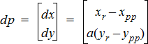
Where:
❙ PIXEL_ASPECT_RATIO = 
❙ VICON_RADIAL = 

❙ PRINCIPAL_POINT = 

Raw 2D point:  = Corrected 2D point:
Calculate the radius as 
Calculate the scale factor 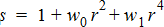
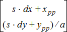
Correct radial distortion  =
= 
Projection matrix
Where:
❙ POSITION = t (3-vector)
❙ ORIENTATION = q (4-vector, quaternion with last component as real part)
❙ FOCAL _LENGTH = f
❙ SKEW = k
Convert the quaternion  to 3x3 rotation matrix
Compose the 3x4 matrix: 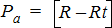
Compose the 3x3 matrix: 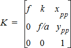
Calculate the 3x4 projection matrix as: 