
 |
Initialize the calibration brim
After you have imported the relevant capture files and blob-detected the take, the next step is to enable CaraPost to initialize the calibration brim that was used on the first frame of the take. The calibration brim is a known pattern of markers that is used to calculate the positions of the cameras.
To initialize the calibration brim:
1. On the Process menu, click Initialize Default Calibration Brim [V2.0].
Tip: If you are using a custom brim, you may need to use a different option.
In the History pane, Initialize Default Calibration Brim is displayed.
2. On the View menu, click New Floating Workspace.
The calibration brim appears in a 3D view.
Tip: To zoom out so you can see the whole calibration brim, in the new workspace, press SHIFT+right-click+drag down.
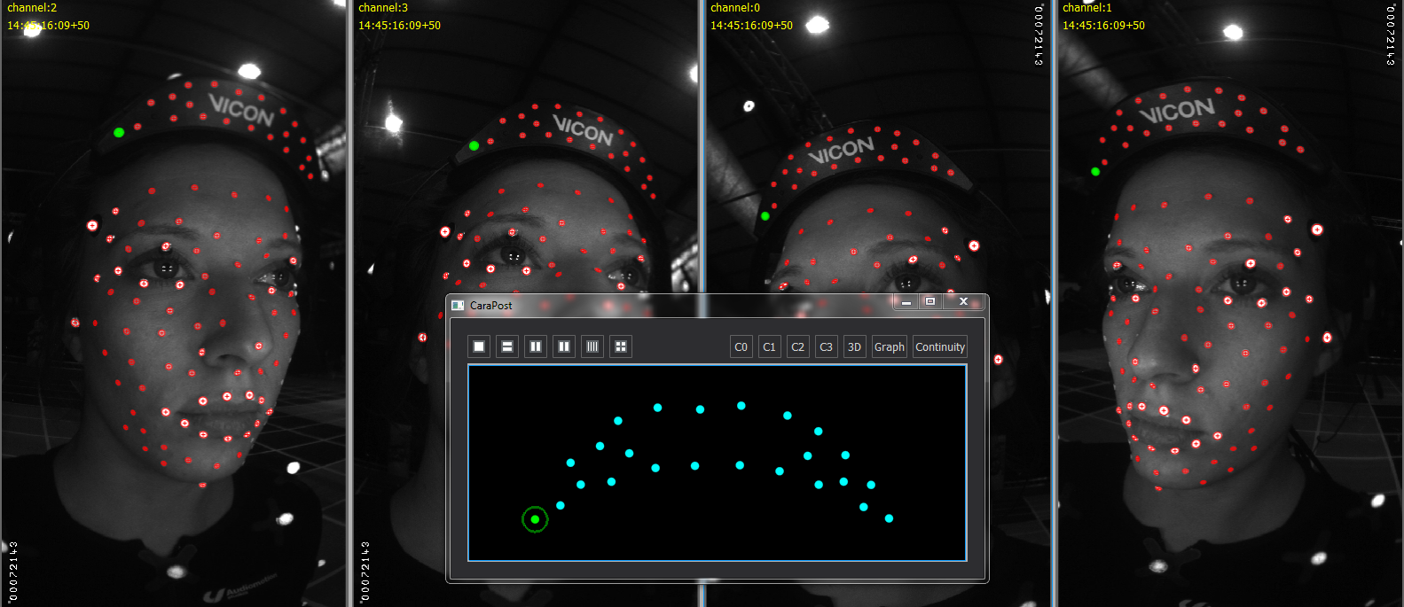
3. Click on the leftmost calibration brim marker in the first camera view so that it turns green. Then CTRL+click the same marker in the other three camera views and in the 3D view so they are all selected:
4.  On the Edit menu, click Merge (or press M).
A correspondence between the blob detections and the 3D model of the calibration brim is created.
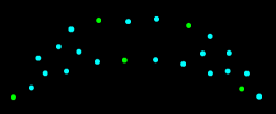
5. Repeat the previous 2 steps to create correspondences for at least four points on the calibration brim in all camera views. The following example shows correspondences for five calibration brim points (displayed in green):
6. To enable Vicon CaraPost to calculate the approximate positions of the cameras, on the Process menu, click Solve Calibration Brim [Manual].
The 3D view should look similar to this:
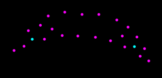
The light blue points are not required, so select and delete them (press CTRL+D).
If necessary, use the following commands to adjust the view:
|
Action |
|
|
ALT+right-click+drag or SHIFT+right-click+drag |
|
|
ALT+click+drag or SHIFT+click+drag |
|
|
ALT+left & right (or middle) button+drag or |
7. To examine the 2D re-projection errors, in a camera view, SHIFT+right-click+drag on a marker in the calibration brim (to keep the marker in the center of the view, you may also need to use SHIFT+left & right (or middle) button+drag).
The view zooms in, so that you can clearly see the 2D and 3D data (slightly enlarged in the following example):
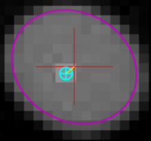
The red cross is the center point of the 2D detection, the blue cross is the center point of the 3D projection and the small yellow line connecting the two is the error.
In the above example the yellow line is short and when we look at the other detections in the same example, the blue crosses all appear over the detections, which indicates that the calibration brim is correctly aligned, as shown in the following image:
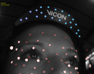
If the yellow lines representing the 2D re-projection errors are long (ie, more than a few pixels in length), this indicates that the calibration brim is not correctly aligned. The probable cause of this is that one or more brim points are mismatched in one or more of the camera views. Before continuing to the next processing step, correct any mismatches and obtain a good brim alignment.
For the next step, see Initialize face marker positions.